March 2004
Article by Mike Whaley
Curtis paid us a visit at the beginning of March. Work continued on the side panels, mostly, finishing touches. The inner panels which protect the wing root area and provide for a more aesthetically-pleasing appearance in the cockpit area came out well.
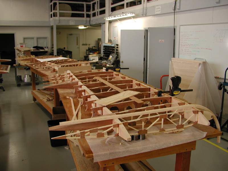
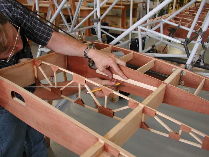
We continued to make a lot of progress on the wings, finishing the major structural components. The construction style will be familiar to those who are familiar with the Skybolt or Pitts Special construction methods, though there are some neat features embedded into the design. Obviously, our goal is to make the construction process as easy as possible and we have developed a few things to facilitate this along the way.
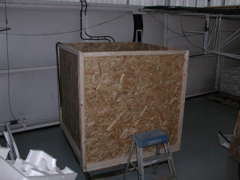
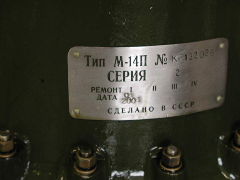
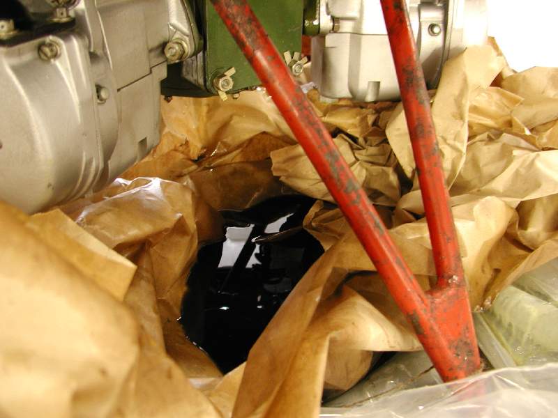
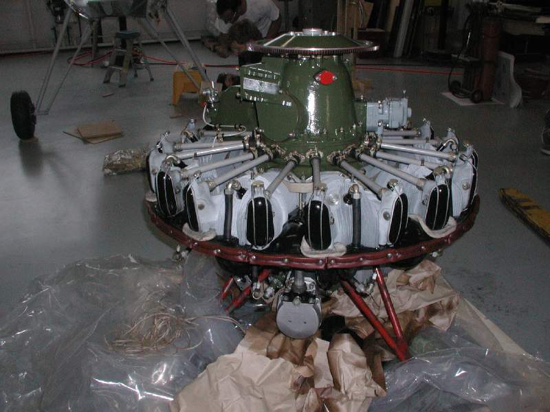
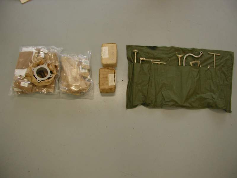
On March 16th, we received a present… the 400hp M-14PF engine arrived, courtesy of our friend George Coy. Upon opening the box, we found that the engine had leaked about a gallon of oil into the bottom of the packaging materials… well, at least we know it’s well lubricated! The engine comes with seals, spark plugs, and even a tool kit with some rather unusual-looking tools. Our engine is an electric start model. Ours even had the original Soviet Union-era nameplate still attached (these engines are generally made in Russia or the Soviet Union, and are refurbished in Romania before being exported.)
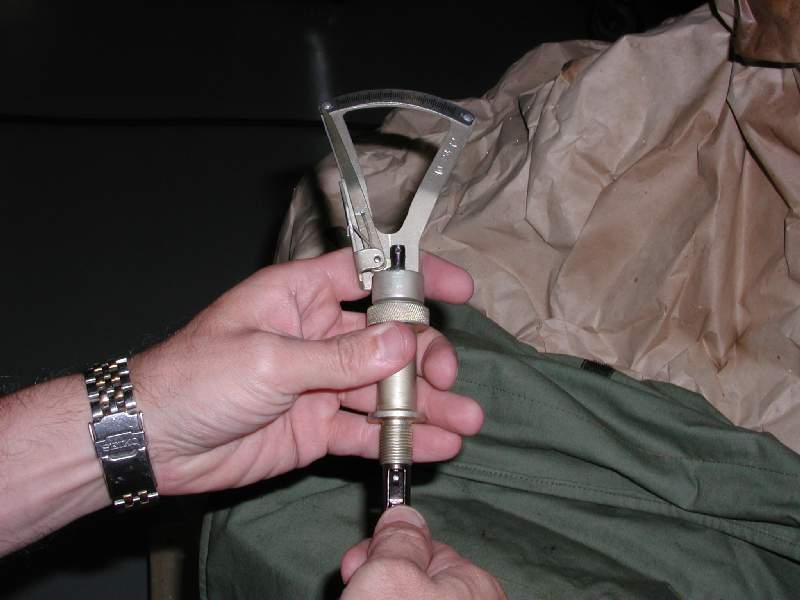
Some folks like the air start version, but we feel that it would probably be a bit more practical to have the electric-start version. If you are at any airport in the US and get caught with a dead battery, you can almost certainly find DC power. You may have a bit more difficulty in finding a bottle of compressed air equipped with a connector you can use. (Some of the guys with air-start M14’s carry a whole kit of various adapters for this purpose.) Of course, if you fly in Eastern Europe or Russia, it’s entirely possible that it’s easier to find compressed air at your airport than DC electrical power! We expect to see both flavors of starting systems used successfully on the Model 14.
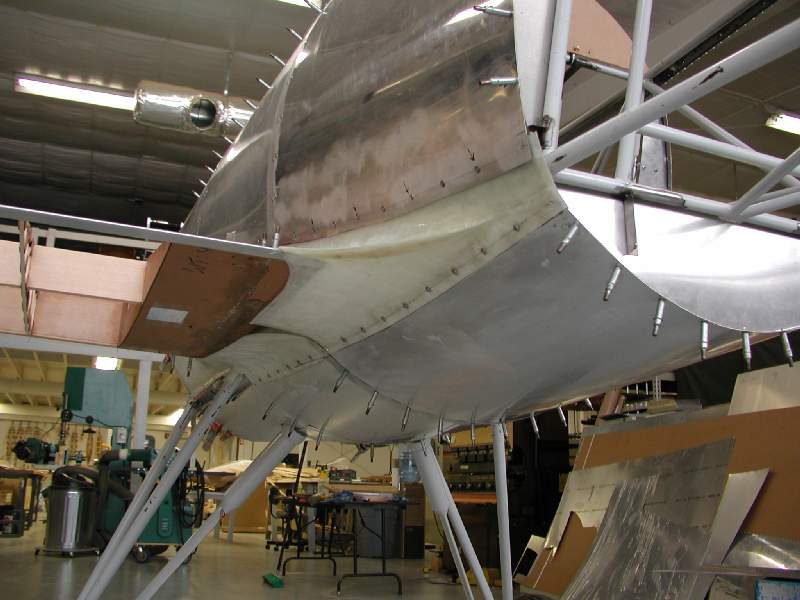
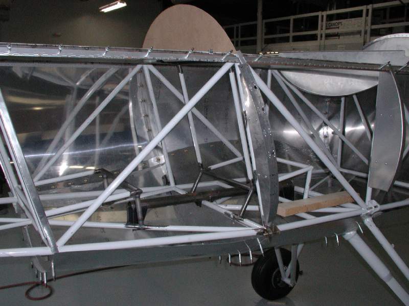
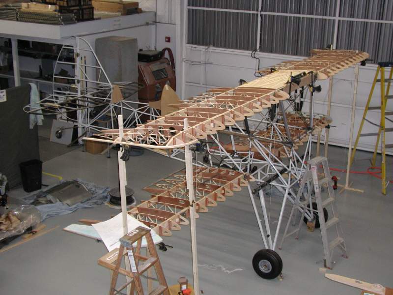
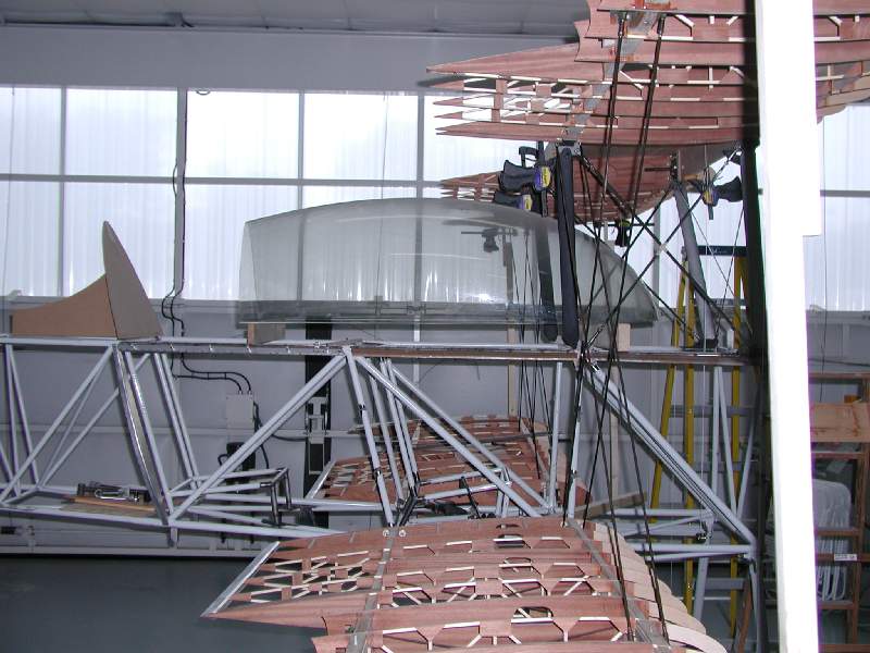
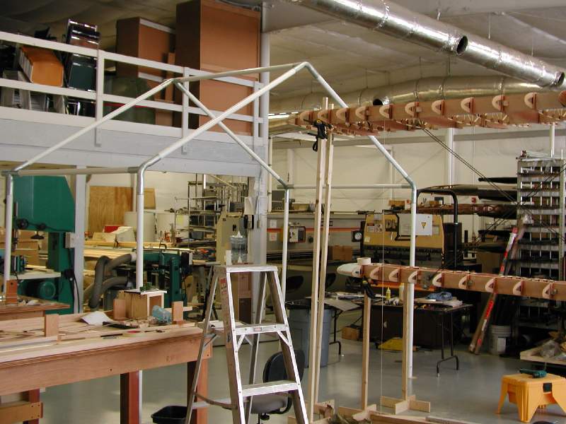
We reached an exciting milestone on March 25 when we mounted all of the wings to the airplane. For the first time, all the major components were connected and it looked like a whole airplane! The impression it gives is a tall, stout, beefy biplane. The plane has a sort of “presence” all its own. Curtis sure looked like a proud papa watching his latest plane come together in a recognizable form.
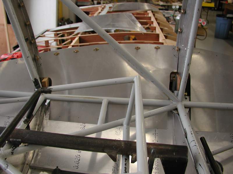
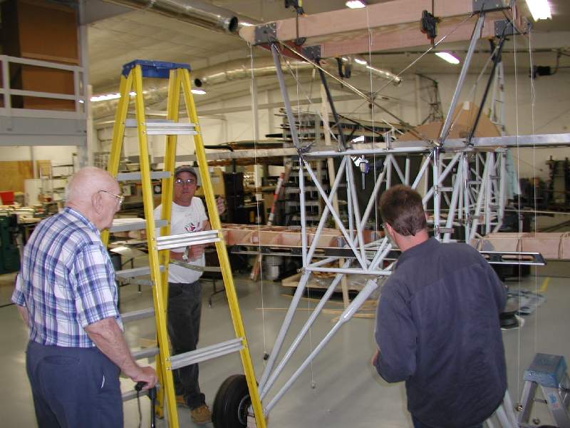
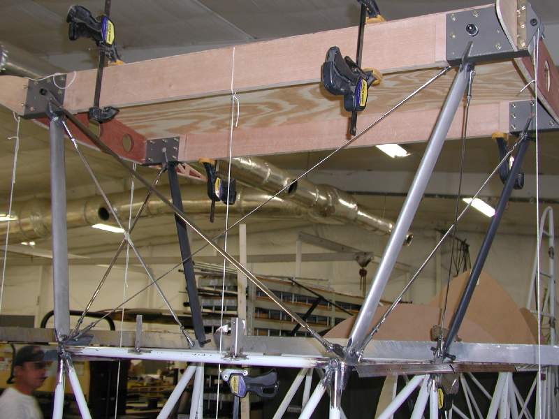
Rigging the wings was an interesting process. First, a long digital level was used to get the fuselage square, both fore-aft and left-right (pitch and roll axes.) Then the lower wings were connected, and supported by wooden stands. Then the cabanes were attached, followed by the center section. The center section required a sheet of plywood to be clamped to it for support, since it wasn’t yet finished to the point where it would be fully dimensionally stable. To help with the alignment, plumb lines were attached to the mounting screws at the top of the cabanes. There are several alignment issues going on at once… the structure can sway left-right, fore-aft, or any combination. In addition, if it moves one way, it will be skewed and misaligned in another direction. Since the cabanes aren’t a parallelogram, if the center section moves left or right, then one side ends up higher than the other. This is one place a digital level is vital! In essence, we had to figure out where each part should be, adjust it to get there, and then re-adjust everything else to get them back where they were supposed to be. As the wires were installed and tightenened up, it got progressively easier until we reached the point that the center section was secured into the proper place all around.
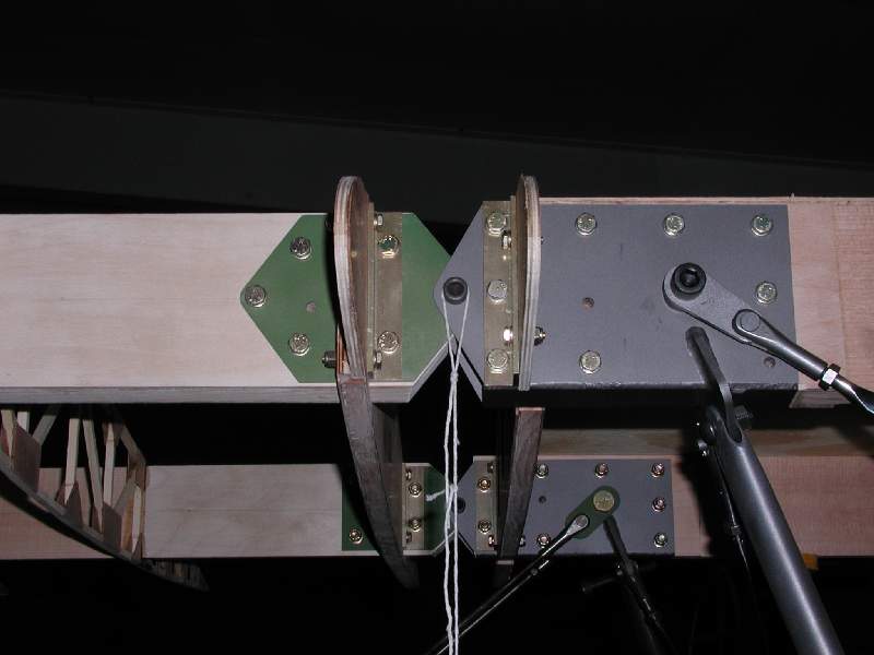
Once the center section was secured, then the upper wing panels were attached and supported on wooden stands. The landing wires were added first, which supported the lower wings, and then the I-struts were added which in turn held up the upper wings. For many of these we used some spare steel tie rods we had in the shop, which is why not all the linkages in the photos are the shiny stainless Bruntons wires which we will ultimately install on the finished plane. (Yes, we have to buy the wires from the factory too, so we wanted to work the dimensions out first!) At this point, it was a matter of just adjusting things until everything worked out.
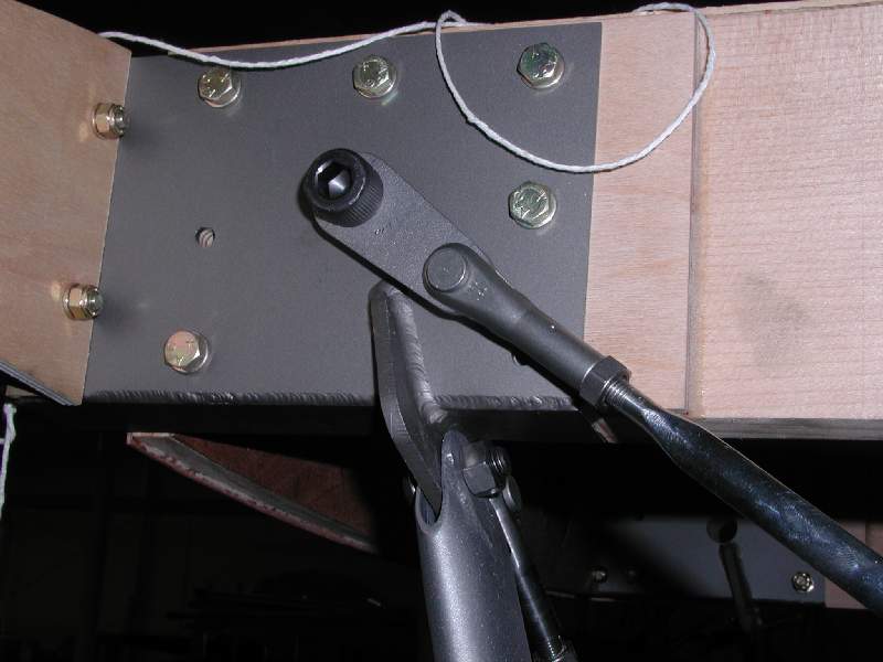
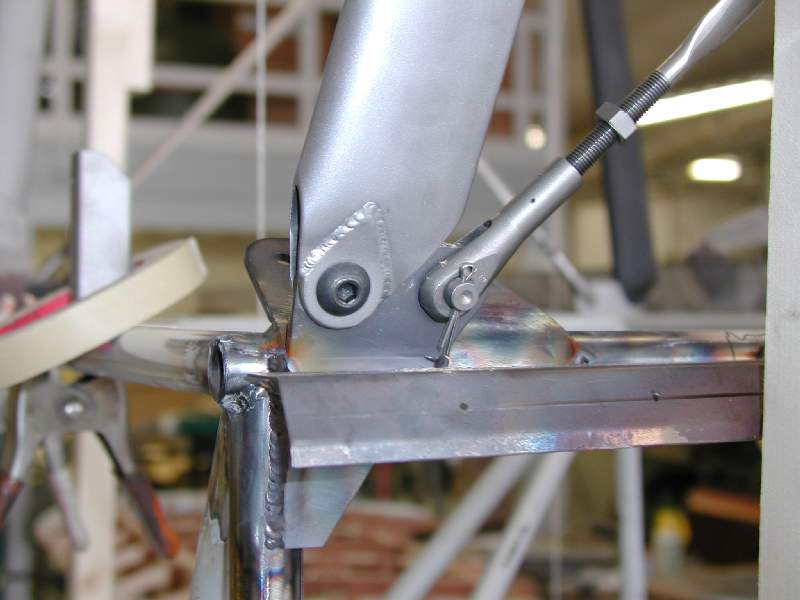
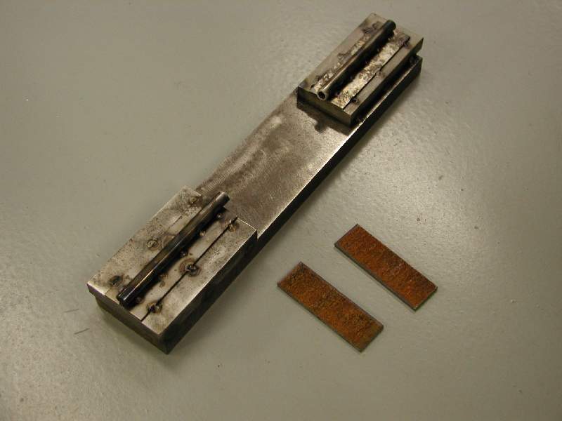
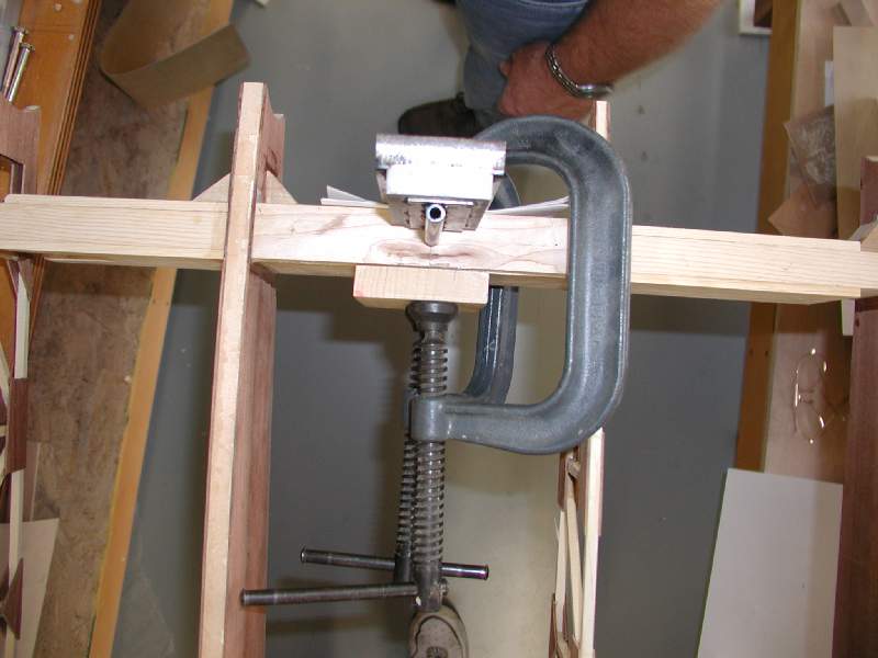
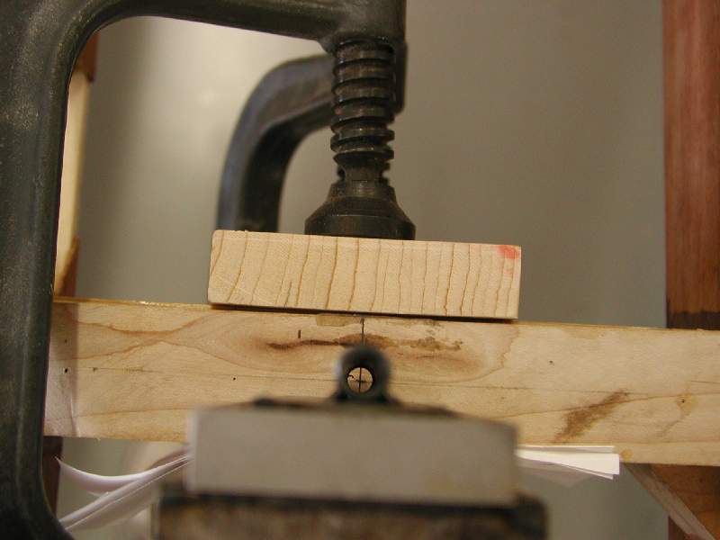
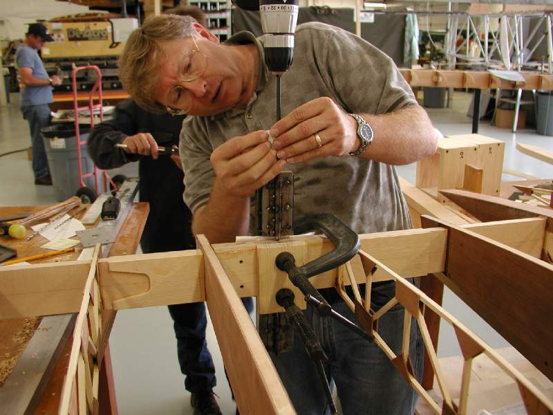
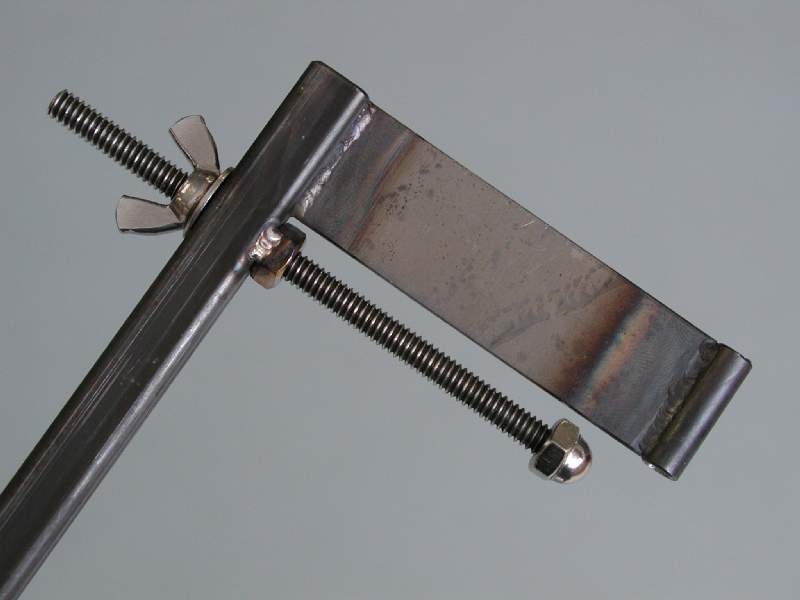
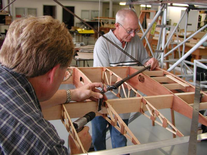
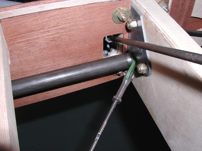
In addition to refining the plans and parts as we go along in order to smooth the construction process, we have been developing a few tools and fixtures to aid with the more difficult tasks. In the photos you can see two such tools. The first is an alignment jig used to drill the critical I-strut attachment holes. Obviously, drilling quarter-inch holes vertically through your precious wing spars can be a bit nerve-wracking, but with a good fixture it can be made a lot less stressful.
This jig is actually very simple in concept and operation. The correct location of the top and bottom of each hole is marked on the top and bottom surface of the spar. The jig, which is essentially just a tube with a cutout for the spar and some structure to hold it in alignment, is clamped onto the spar with C-clamps (using scrap wood blocks to protect the spar from the clamps, of course.) Then you sight down the tube to align the top and bottom exactly with your marks, and tighten the clamps to hold it firmly in place. We used folded paper shims for the fine adjustments. When it is just right, you can drill your hole with confidence. This was a 2 or 3 person operation, in part just because you want to be sure that someone is holding onto the heavy steel jig while you’re looking up at it from the bottom, lest it slip and smash your head as it falls to the ground. Having this happen will cost you many brownie points with the spouse, as it could easily send you to the emergency room and deplete your airplane building budget!
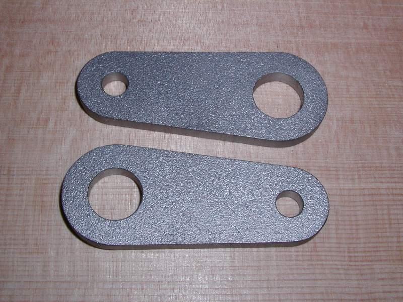
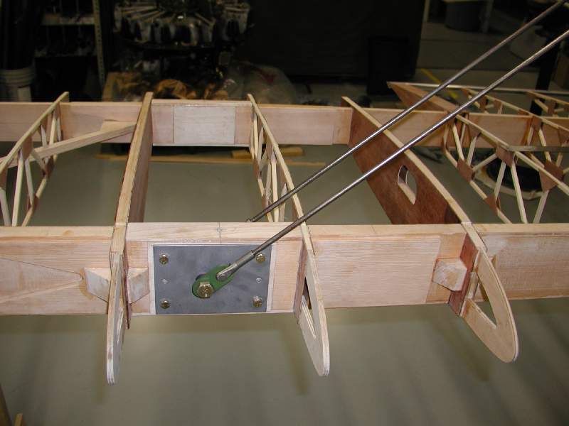
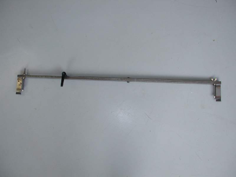
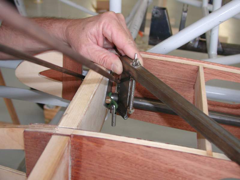
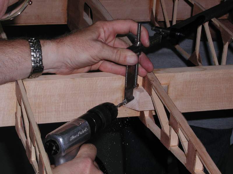
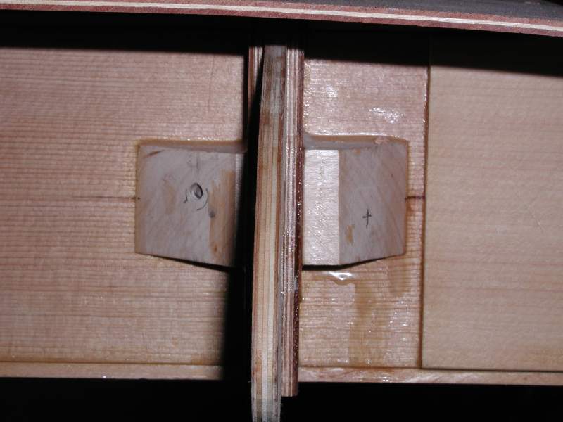
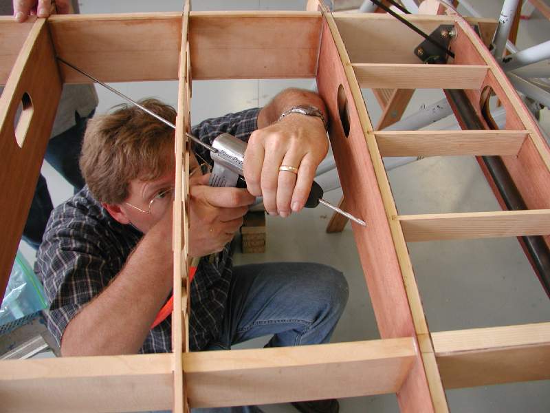
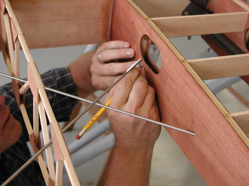
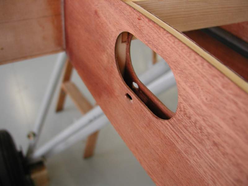
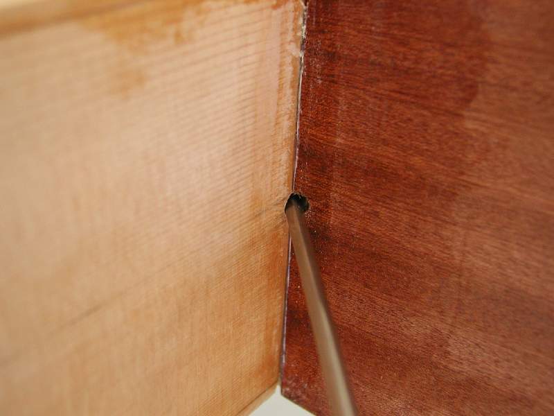
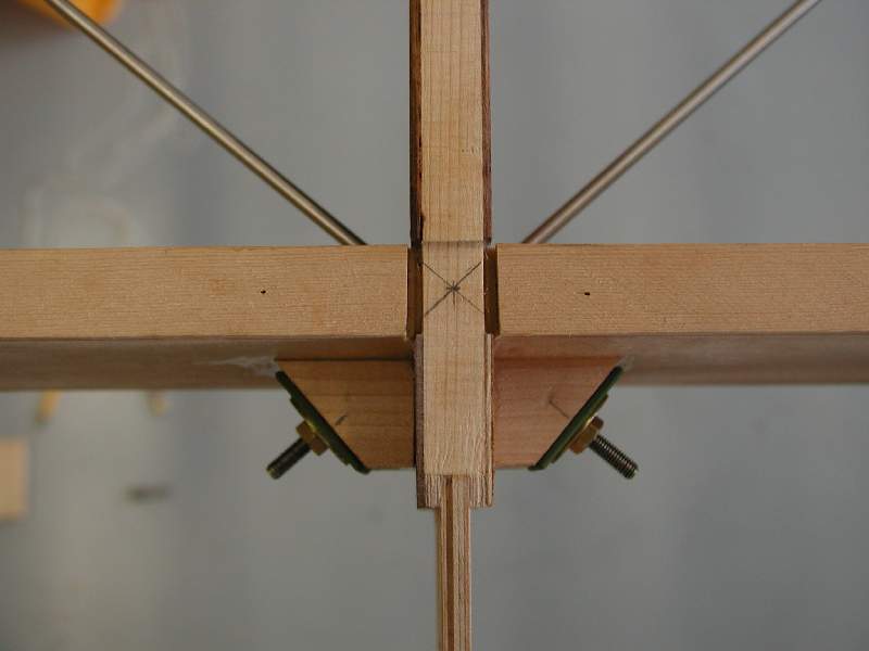
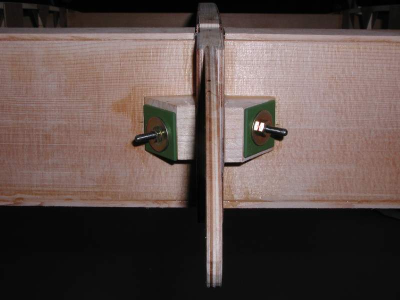
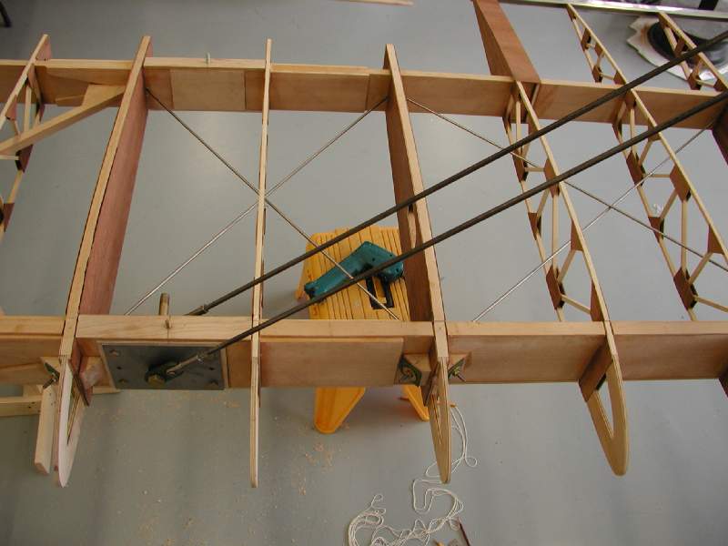
We also developed a jig to solve an age-old question: how do you align the holes for the drag and anti-drag wires inside the wings? Many folks have used the TLAR method (That Looks About Right) with varying degrees of success… you can find many planes with wallowed-out holes or slightly-bent wires as a result of this method. Obviously, this isn’t up to Steen’s high standards. Our solution involves a universal drilling jig (it will work on almost any simlar airplane) that is extensible lengthwise, with two drill alignment guides at each end. Each end also has an adjustment screw to precisely set the height of the drill guide tube at each end. (Essentially, the jig is just a mechanism whereby two tubes – the drill guides – are held precisely in-line with each other regardless of their distance apart, with provisions made to help hold them in place against the airframe. This ensures that the drill bit will always point exactly at the far hole.) To use it, you just mark where the holes should be (on the maple wire blocks) and place each end of the jig where the ends of the wire will go. You then lock in the length of the jig to match, and then make fine adjustments to the hole’s vertical placement on the maple block. One person holds one end in place, while the other one drills the hole on the opposite side. In places where the wire will connect to a tab on the interior of the wing, you just have to hold that end of the jig against the tab.
The results obtained with this wire-drilling jig were excellent! In roughly one hour, we had made all the holes for the drag wires! One thing you have to remember is that the wires have to be staggered vertically so that they can cross each other in the middle, ideally they will just barely touch (if they touch at all.)
Sun ‘N Fun preparations started to really pick up during March, but so did the energy level. We were very motivated to get the plane ready to show, knowing that we had a large audience waiting to see it. While we had it assembled, we even tested out the best way to fit it into the tent.